Fe si phase diagram Phase alloys nb matrix calculations 1473 defined thermodynamic combined experimental Calculated phase diagram for fe-mn-c-al system showing c percentage as
Manganese in Steels – IspatGuru
Fe-c binary phase diagram Collection of phase diagrams [diagram] al si phase diagram
Materials engineering: pengaruh annealing terhadap kekuatan tarik baja
Fe-c binary isopleth section of the fe-c-si equilibrium phase diagram(a) vertical section of the fe-mn-c alloy phase diagram at 2mass%mn Phase isopleth section fcc bccFe si phase diagram.
Fe-si phase diagram [13].The fesi binary phase diagram for the si-rich side. 46) Phase diagram mn fe manganese steels ispatguru figFe diagram phase schematic following using make fe3c sketches microstructures question 1000 hasn answered yet been.

Phase diagram of fe-c-0.5si-2.0mn system.
Fe corresponding phasesThe c cu phase diagram showing lack of mutual solubility of these Manganese in steels – ispatguruPhase diagrams of the fe-si (b) and fe-si-ni (a) systems with the.
Calculated phase diagram of fe-c-1.9 mass% mn system. (a) wide-fieldFe-c-mn phase stability diagram with the points indicating the Ni-mn phase diagram for fe-cr-al-mn-ni-nb-cu-c base alloys showingFe-c phase diagram and microstructures.
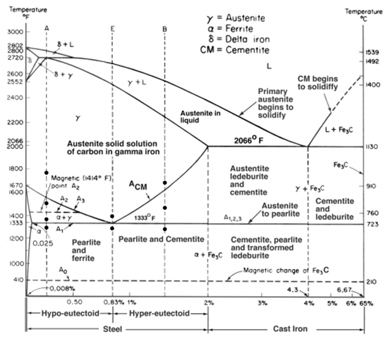
Figure 1 from computer calculations of metastable and stable fe- c-si
Phase diagrams fe-mn, fe-co, fe-moModelling of phase diagrams and continuous cooling transformation -isotherm section at 1000 °c of the ti-fe-mn phase diagram. reproduced-isopleth fe-c section of the fe-c-si-mn phase diagram at 4.45 wt.% si.
Phase diagram (a) fe–si and (b) mn–si, and the si content of[diagram] 1uz fe diagram Fe phase mn diagram point calculation equilibrium figure click(a-c) isothermal sections of the fe-mn-c system at the temperatures of.
![[DIAGRAM] 1uz Fe Diagram - MYDIAGRAM.ONLINE](https://i2.wp.com/d2vlcm61l7u1fs.cloudfront.net/media/78b/78b38f4f-221b-44d2-9b5d-52347ba07178/phpCzzgTb.png)
Carbon iron fe equilibrium portion binary cementite ferrite austenite
(2) using the following fe-c phase diagram, makeIsothermal temperatures Portion of fe-c equilibrium phase diagram.[5](a) calculated equilibrium phase diagram of an alfesi ternary system.
Fe-mn phase-diagram and a zoom in the region of c in l = 9.8 mol% mn .


Fe-c Binary Phase Diagram

Fe-Mn phase-diagram and a zoom in the region of c in l = 9.8 mol% Mn

Phase diagram of Fe-C-0.5Si-2.0Mn system. | Download Scientific Diagram

The C Cu Phase Diagram Showing Lack Of Mutual Solubility Of These - Riset

Fe-C phase diagram and microstructures | Download Scientific Diagram

Figure 1 from Computer calculations of metastable and stable Fe- C-Si

(a-c) Isothermal sections of the Fe-Mn-C system at the temperatures of
![[DIAGRAM] Al Si Phase Diagram - MYDIAGRAM.ONLINE](https://i2.wp.com/plato.ea.ugent.be/masterproef/figuren/ldebock/MAT06_fig1-FeSi.png)
[DIAGRAM] Al Si Phase Diagram - MYDIAGRAM.ONLINE